13+ diagram of hydraulic cylinder
O Ring 12 2. Parker Engineering Your Success Motion Control Technology.
Huatong Catalogue Part2 Actuator Components Pneumatic Hydraulic English
Oil Tube 14 4.

. Hydraulic Cylinder Parts Diagram hydraulic cylinder parts diagram hydraulic cylinder parts Hydraulic Cylinders Hydraulic Cylinders Limit Valve Hydraulic cylinder Contact Us Tel. RC5013 552 ton Capacity 1325 in Stroke General Purpose Hydraulic Cylinder RC-Series Hydraulic Cylinders are incredibly durable and versatile. Whether your application is manufacturing automotive construction agriculture forestry or.
Use keywords or part numbers instead of full sentences for best results. Tie-Rod 2500 PSI 152 Tie-Rod 3000 PSI 145 Top Link 5 Welded Clevis 101 Welded Log Splitter 3 Welded Pineye 59 Welded Swivel Mount 33. THE GANNON CYLINDER AS IT IS CALLED IN THE FIELD IS GENERALLY FOUND ON BOX SCRAPERS MOWERS BLADES AND.
A simple diagram below helps explain the mechanics of the process -- as fluid enters a chamber more force is applied to push or pull the piston rod in or out of the cylinder. Parker manufactures a diverse range of standard and special tie rod roundline and mill type. A single-acting cylinder is simplest in design and is shown schematically in Fig11.
Parker is the worlds largest supplier of hydraulic cylinders and parts for industrial applications. 13-534 - gannon hydraulic cylinder0166 - 1282 catalog search note. Basic hydraulic theory cross mfg system components parts design circuit diagram the real value of diagrams fluid power journal press brake ultimate guide machinemfg.
GANNON CYLINDER SEAL KIT. 737-3025 1234 filter oil. It consists of a piston inside a cylindrical housing called barrel.
Pressure Relief Valve PRV 15 5. On one end of the piston there is a rod which. Work is performed during forward motion as well as backward.
Elbow Fitting 13 3. Lock Nut 16 6. Bailey designs manufactures and sources the highest quality hydraulic cylinders available.
Rephasing also allows air to be. The rephasing passageway enables the cylinders to rephase operating evenly to raise and lower an implement to the desired working depth. 1 John Deere Hydraulic System Diagram with Parts Details.
These single acting hydraulic. In double acting Hydraulic cylinder the pressurized liquid is admitted on both sides of the piston alternately.

Shows A Schematic Diagram Of A Hydraulic Cylinder The Cylinder Piston Download Scientific Diagram

Hydraulics And Automation Blog Wake Industrial

Hydraulic Cylinder An Overview Sciencedirect Topics

Calameo Komatsu Pc300lc 5 Lc 5k Hd5 Pc300 Lc 5 Migty Pc400 Lc Hd 5 Pc400 Lc 5 Migty Skachat Na Www Imparts55 Ru

Hydraulic Cylinder Parts Diagram Quizlet

Sumitomo Sh350lc 5 Sh350hd 5 Sh370hd 5 Hydraulic Excavator Service Text Manual Wlst3505 01t Pdf By Heydownloads Issuu
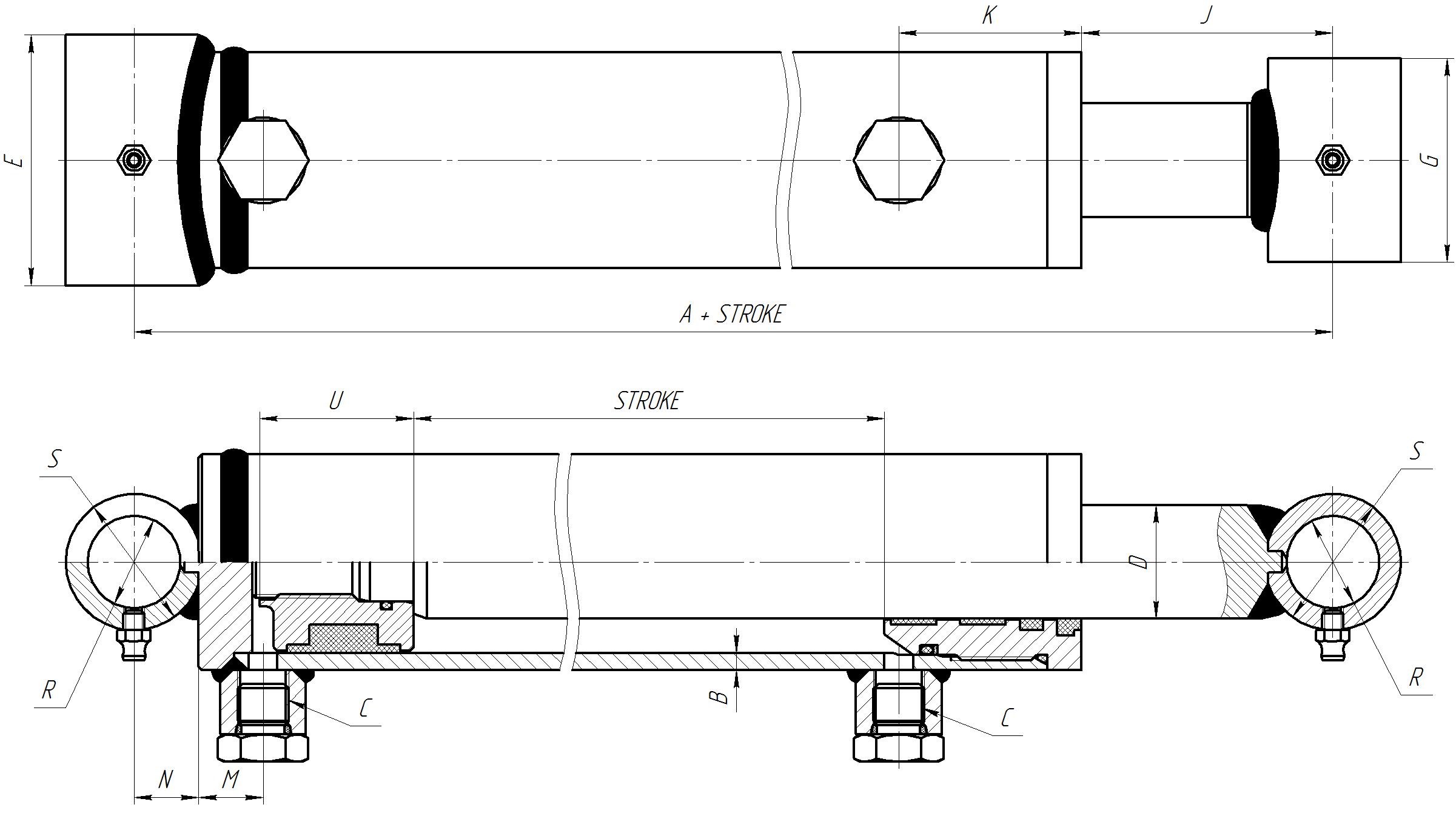
How To Measure A Hydraulic Cylinder Replacement Magister Hydraulics

Multiplexing Of Electrospray Ionization Sources Using Orthogonal Injection Into An Electrodynamic Ion Funnel Analytical Chemistry
Full Title For Class 305 Subclass 111

Catalog Bazhydraulic Ou

Hitachi Zx135us 5a Hydraulic Excavator Electrical Hydraulic Circuit Diagram By Heydownloads Issuu

Double Acting Cylinder Diagram Types Symbol
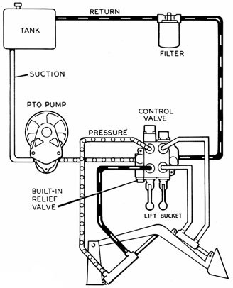
Hydraulics Systems Diagrams And Formulas Cross Mfg

Ion Mobility Mass Spectrometry Jiang Major Reference Works Wiley Online Library

Double Acting Cylinder Diagram Types Symbol

Double Acting Cylinder Diagram Types Symbol

Schematic Diagram Of Hydraulic Cylinder Structure Download High Quality Scientific Diagram